Ram BOP
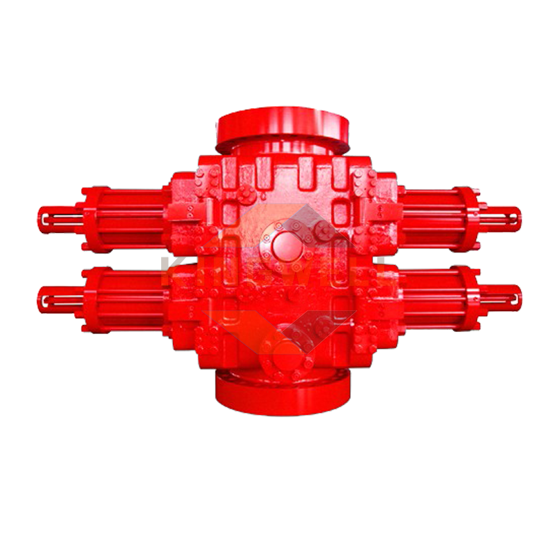
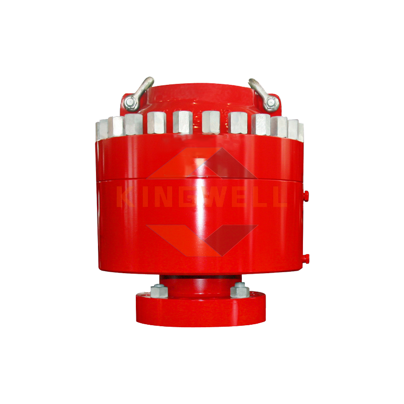
Ram BOP is a field-proven product that is designed for a variety of operations, from overhaul to high pressure, critical maintenance operations to onshore drilling and subsea maintenance. The ram BOP preventer consists of the following elements: cast steel body, die grooves, hydraulic cylinder assemblies, dies, die rod, die rod seal, indicator system, etc.
The dimensions of the ram BOP upper, lower and outlet nozzles are in accordance with the specification for oil and gas drilling equipment according to the requirements of API 16A. Made of high-strength alloy steel, the parts working under pressure (such as the ram BOP housing, cover, etc.) are formed through external refining and proper heat treatment, preventing the ingress of harmful chemical components and non-metallic inclusions strictly from the materials and ensuring safety and reliability of the spot preventer. The piston chamber of the hull uses a long runway to reduce stress concentration. Both the hood switch and the piston switch are actuated by hydraulic pressure and share the same oil line. The cap uses the same oil line and piston opening and closing operation. In addition, the lid uses the same oil line and plunger closing and opening operation.
Ram BOP has 3 types: single-ram BOP, double-ram BOP and triple-ram BOP. The double-ram BOP can be closed with a manual control wheel, but it is not possible to open the dies manually due to the fact that the screw connection is only one-sided. As a rule, the BOP unit includes a working BOP with tube dies and a backup BOP with blind dies.
Technical Parameters of Ram BOP
| Type | Bore size mm(in) | Rated operating pressure Mpa(psi) | Volume to open chamber L | Volume to close chamber L | Cloure type | Closure range | Dimensions | Weight, kg | |||||
| Length mm | Width mm | Height,mm | SingleY | DubleS | |||||||||
| SingleY | DubleS | ||||||||||||
| 7 1/16'' 3000PSI | (2) FZ18-21 | 179.4 7 1/16 | 21 (3000) | 1.6 | 2 | H | 0-5 9/16 | 1420 | 645 | 568 | 854 | 855 | 1540 |
| 7 1/16'' 5000PSI | (2) FZ18-35 | 179.4 7 1/16 | 35 (5000) | 1.6 | 2 | H | 0-5 9/16 | 1420 | 645 | 624 | 910 | 895 | 1580 |
| 7 1/16'' 10000PSI | (2) FZ18-70 | 179.4 7 1/16 | 70 (10000) | 2.2 | 2.5 | H | 0-5 9/16 | 1720 | 640 | 897 | 1262 | 1660 | 3020 |
| 7 1/16'' 15000PSI | (2) FZ18-105 | 179.4 7 1/16 | 105 (50000) | 7.4 | 8 | H | 0-5 1/2 | 1988 | 820 | 922 | 1372 | 3175 | 5885 |
| 9'' 3000PSI | (2) FZ23-21 | 228.6 9 | 21 (3000) | 1.3 | 1.5 | HF | 0-7 | 1526 | 565 | 580 | 866 | 705 | 1250 |
| 9'' 5000PSI | (2) FZ23-35 | 228.6 9 | 35 (5000) | 4.7 | 5.3 | HF | 0-7 | 2036 | 720 | 805 | 1190 | 1830 | 3415 |
| 9'' 10000PSI | (2) FZ23-70 | 228.6 9 | 70 (10000) | 27 | 8 | H | 0-7 | 2324 | 850 | 1038 | 1518 | 3635 | 6835 |
| 9'' 15000PSI | (2) FZ123-105 | 228.6 9 | 105 (50000) | 10.2 | 10.9 | HF | 0-7 | 2170 | 920 | 1140 | 1640 | 4150 | 7500 |
| 11'' 3000PSI | (2) FZ28-21 | 279.4 11 | 21 (3000) | 2.7 | 3.2 | S | 0-8 5/8 | 1846 | 675 | 740 | 1100 | 1400 | 2550 |
| 11'' 5000PSI | (2) FZ28-35 | 279.4 11 | 35 (5000) | 7 | 68 | H | 0-8 5/8 | 2265 | 785 | 895 | 1325 | 2475 | 4550 |
| 11'' 10000PSI | (2) FZ28-70 | 279.4 11 | 70 (10000) | 14.6 | 16.7 | H | 0-8 5/8 | 2324 | 850 | 1102 | 1582 | 3770 | 6850 |
| 11'' 15000PSI | (2) FZ28-105 | 279.4 11 | 105 (50000) | 10.2 | 10.9 | HF | 0-8 5/8 | 2650 | 1050 | 1244 | 1784 | 6303 | 11028 |
| 13 5/8'' 3000PSI | (2) FZ35-21 | 346.1 13 5/8 | 21 (3000) | 7.8 | 8.9 | S | 0-10 3/4 | 2414 | 760 | 774 | 1164 | 2705 | 5115 |
| 13 5/8'' 5000PSI | (2) FZ35-35 | 346.1 13 5/8 | 35 (5000) | 7.9 | 9.3 | S | 0-10 3/4 | 2415 | 847 | 930 | 1370 | 3010 | 5480 |
| 13 5/8'' 10000PSI | (2) FZ35-70 | 346.1 13 5/8 | 70 (10000) | 18 | 20.7 | HF | 0-10 3/4 | 2786 | 1085 | 1276 | 1782 | 6120 | 11135 |
| 13 5/8'' 15000PSI | (2) FZ35-105 | 346.1 13 5/8 | 105 (50000) | 17.4 | 20 | H | 0-10 3/4 | 3074 | 1140 | 1420 | 1985 | 8945 | 16070 |
| 16 3/4'' 5000PSI | (2) FZ43-35 | 425.5 16 3/4 | 35 (5000) | 10.3 | 11.6 | HF | 0-10 3/4 | 2923 | 1190 | 1090 | 1570 | 5300 | 9860 |
| 18 3/4'' 5000PSI | (2) FZ48-35 | 476.3 18 3/4 | 35 (5000) | 24.5 | 27.9 | HF | 0-16 | 3430 | 1440 | 1504 | 2072 | 9758 | 12286 |
| 18 3/4'' 10000PSI | (2) FZ48-70 | 476.3 18 3/4 | 70 (10000) | 24.5 | 27.9 | HF | 0-16 | 3430 | 1440 | 1618 | 2186 | 10312 | 20624 |
| 20 3/4'' 3000PSI | (2) FZ53-21 | 527.1 20 3/4 | 21 (3000) | 12.2 | 13.6 | HF | 0-16 | 3424 | 1165 | 1065 | 1650 | 6130 | 13355 |
| 21 1/4'' 2000PSI | (2) FZ54-14 | 539.8 21 1/4 | 14 (2000) | 12.1 | 13.8 | HF | 0-16 | 3300 | 1130 | 940 | 1480 | 5560 | 10200 |
| 21 1/4'' 3000PSI | (2) FZ54-21 | 539.8 21 1/4 | 21 (3000) | 26 | 29.6 | HF | 0-16 | 3590 | 1445 | 1320 | 1950 | 9270 | 17670 |
| 26 3/4'' 3000PSI | (2) FZ68-21 | 679.5 26 3/4 | 21 (3000) | 32.6 | 37 | HF | 0-18 5/8 | 4350 | 1450 | 1250 | 1870 | 12360 | 20290 |
Technical features of Ram BOP
- Design and manufacture of ram BOP according to API Spec 16A.
- Corrosion-resistant working bodies inside the ram BOP that come into contact with aggressive media (hydrogen sulfide) are made in accordance with the requirements of NACE MR-175.
- Pressure support made of high-quality alloy steel
- High BOP Side Door Combinatorial Seal, Under Pressure From The Well Sealing Is Better
- The use of floating and whole dies, the sealing is reliable and the change is convenient
- Application of concealing lubrication channel,holding and hydraulic joints are separate
- The design of the hinge is simple and the change is convenient
- A large circle is applied to the sides of the hull cavity, the radian is transient on all sides, and the peak pressure of the casing is reduced
- The design of the ram BOP is compact, compared to its counterpart abroad, the dimensions are smaller
- In the cold-resistant spot preventer it is possible to work out the steam channel, steam flow is made, heat radiation is made (Bybor according to customer's requirement)
Online consultation
Quick access to Technical Support and Detailed Quotations
CONTACT US
-
This email address is being protected from spambots. You need JavaScript enabled to view it. -
+86 315 2031752
